Hydraulic machinery Wikipedia
A hydraulic system uses an incompressible liquid as its fluid, The valve block will be mounted to the machine's frame with a three point pattern to avoid distorting the valve block and jamming the valve's sensitive components The spool position may be actuated by mechanical levers, hydraulic pilot pressure, or solenoids which push the spool left or right A seal allows part of the spool A block diagram is a diagram of a system in which the principal parts or functions are represented by blocks connected by lines that show the relationships of the blocks They are heavily used in engineering in hardware design, electronic design, software design, and process flow diagrams Block diagrams are typically used for higher level, less detailed descriptions that are intended to Block diagram WikipediaA functional flow block diagram (FFBD) is a multitier, timesequenced, stepbystep flow diagram of a system ’s functional flow The term "functional" in this context is different from its use in functional programming or in mathematics, where pairing "functional" with "flow" would be ambiguousFunctional flow block diagram WikipediaCutaway side view diagram Axial piston pump 3D Render with the parts labeled 3DAnimation An axial piston pump has a number of pistons (usually an odd number) arranged in a circular array within a housing which is commonly referred to as a cylinder block, rotor or barrel This cylinder block is driven to rotate about its axis of symmetry by an integral shaft that is, more or less Axial piston pump WikipediaBlock diagram Wikipedia A block diagram is a diagram of a system in which the principal parts or functions are represented by blocks connected by lines that show the relationships of the blocks They are heavily used in engineering in hardware design, electronic design, software design, and process flow diagrams Block diagrams blok diagram hydraulic system wikipedia,

Basic Hydraulic System Components / Parts,Design
Symbol Of Pressure Control Valve Used In Hydraulic System Circuit Diagram 6 Flow Control Valve A flow control valve is used for adjusting the flow rate of a fluid in a pipeline The valve contains a flow passage or a port whose area can be varied Symbol Of Flow Control Valve Used In Hydraulic System Circuit Diagram 7 Directional control valve Types of directional control valve I Figure 28 Line Diagram of Simple Hydraulic Power System With an understanding of the principles involved in reading fluid power diagram, any diagram can be interpreted Figure 29 shows the kind of diagram that is likely to be encountered in the engineering field To read this diagram, a stepbystep interpretation of what is happening in the system will be presented Figure 29 Typical Fluid Hydraulic and Pneumatic PID Diagrams and Schematics The above system shows a front end loader powered by a PTO driven pump A 2spool directional control valve with builtin relief controls the lift and bucket cylinders of the loader A return line filter is used to prevent contamination Winch The diagram shows a winch powered by a hydraulic motor The directional control valve with builtin relief features optional flow control to control Hydraulics Systems Diagrams and Formulas Cross MfgAn example of this is the function block diagram, one of five programming languages defined in part 3 of the IEC 61131 (see IEC 611313) standard that is highly formalized (see formal system), with strict rules for how diagrams are to be built Directed lines are used to connect input variables to block inputs, and block outputs to output variables and inputs of other blocksBlock diagram WikipediaFunctions of a system pictured by blocks; input and output elements of a block pictured with lines ; the relationships between the functions, and; the functional sequences and paths for matter and or signals; The block diagram can use additional schematic symbols to show particular properties Functional block diagrams have been used in a wide range applications, from systems engineering to Functional block diagram Wikipedia

Block Diagram For Hydraulic Control System – Block Diagram
This photo about: Block Diagram Control System, entitled as Block Diagram For Hydraulic Control System Block Diagram Control System also describes Block Diagram for Hydraulic Control System and labeled as: ], with resolution 2296px x 3373px The block diagram is to represent a control system in diagram form In other words, practical representation of a control system is its block diagram It is not always convenient to derive the entire transfer function of a complex control system in a single function It is easier and better to derive the transfer function of the control element connected to the system, separatelyBlock Diagrams of Control System Electrical4UBlock Diagram Hydraulic System Keywords: Get free access to PDF Ebook Block Diagram Hydraulic System PDF Get Block Diagram Hydraulic System PDF file for free from our online library Created Date: 8/11/2020 10:57:11 PMBlock Diagram Hydraulic SystemBlock diagram of hydraulic brake system 3 0233 Diagram of pneumatic part of handbrake 1 0245 Block diagram of control of trailer brake 0248 Block diagram of oil pressure control 0256 Automatic load control brake 0258 Springloaded unit 0259 Brake booster valve BV3F 0260 Two circuit master cylinder 0261 Wheel brake front 0263 Wheel brake rear 0265 Wheel cylinder W50 Block diagram of hydraulic brake system 2The above system shows a front end loader powered by a PTO driven pump A 2spool directional control valve with builtin relief controls the lift and bucket cylinders of the loader A return line filter is used to prevent contamination Winch The diagram shows a winch powered by a hydraulic motor The directional control valve with builtin relief features optional flow control to control Hydraulics Systems Diagrams and Formulas Cross Mfg

Basic Hydraulic System Components / Parts,Design
Symbol Of Pressure Control Valve Used In Hydraulic System Circuit Diagram 6 Flow Control Valve A flow control valve is used for adjusting the flow rate of a fluid in a pipeline The valve contains a flow passage or a port whose area can be varied Symbol Of Flow Control Valve Used In Hydraulic System Circuit Diagram 7 Directional control valve Types of directional control valve I Figure 28 Line Diagram of Simple Hydraulic Power System With an understanding of the principles involved in reading fluid power diagram, any diagram can be interpreted Figure 29 shows the kind of diagram that is likely to be encountered in the engineering field To read this diagram, a stepbystep interpretation of what is happening in the system will be presented Figure 29 Typical Fluid Hydraulic and Pneumatic PID Diagrams and Schematics • The hydraulic system uses incompressible fluid which results in higher efficiency • It delivers consistent power output which is difficult in pneumatic or mechanical drive systems • Hydraulic systems employ highdensity incompressible fluid The possibility of leakage is less in a hydraulic system as compared to that in a pneumatic system The maintenance cost is less • These Hydraulic Systems Introduction, Working Principle more!A functional block diagram, in systems engineering and software engineering, is a block diagram It describes the functions and interrelationships of a system Functional block diagram of the attitude control and maneuvering electronics system of the Gemini spacecraft June 1962Functional block diagram WikipediaA functional block diagram is a block diagram, that describes the functions and interrelationships of a system The functional block diagram can picture: Functions of a system pictured by blocks; Input and output elements of a block pictured with lines, and ; Relationships between the functions; Functional sequences and paths for matter and or signals; The block diagram can use additional Function model Wikipedia
Hydraulic Diagrams You Should Not Do Without Hydraulics
Consider the four main types of hydraulic diagrams in common use and the consequences of having to manage without them: Block Diagrams show the components of a hydraulic circuit as blocks joined by lines, which indicate connections and/or interactions Cutaway Diagrams show the internal construction of hydraulic components and their flow pathsThis photo about: Block Diagram Control System, entitled as Block Diagram For Hydraulic Control System Block Diagram Control System also describes Block Diagram for Hydraulic Control System and labeled as: ], with resolution 2296px x 3373pxBlock Diagram For Hydraulic Control System – Block Diagram Hydraulic drive system Wikipedia A hydraulic drive system is a quasi hydrostatic drive or transmission system that uses pressurized hydraulic fluid to power hydraulic machinery The term hydrostatic refers to the transfer of energy from pressure differences not from the kinetic energy of the flow Bleeding Air from a Hydraulic System Hydraproducts Broadly speaking over time air will proces diagram of hydraulic sistems Les 6 QuartsHAWE Hydraulics Pvt Ltd No 68, Industrial Suburb 2nd Stage, Yeshwanthpur Bangalore 560 022, India India Phone: +91 80 Fax: +91 80 Block diagram HAWE Hydraulics IndiaBasic Hydraulic System Although hydraulic circuit layouts may vary significantly in different applications, many of the components are similar in design or function The principle behind most hydraulic systems is similar to that of the basic hydraulic jack Oil from the reservoir is drawn past a check ball into the piston type pump during the piston's upstroke When the piston in the pump is Hydraulic Systems Basics DPHU
Hydraulics Systems Diagrams and Formulas Cross Mfg
The diagram shows a winch powered by a hydraulic motor The directional control valve with builtin relief features optional flow control to control the speed of the winch The hydraulic pump and motor must be matched to the torque requirements of the winch Hydrauliccircuit diagrams are complete drawings of a hydraulic circuit Included in the diagrams is a description, a sequence of operations, notes, and a components list Accurate diagrams are essential to the designer, the people who build the machine, and the people who maintain the hydraulic system There are four types of hydrauliccircuit diagrams They are block, cutaway, Basics of Hydraulics and Hydraulic Systems – IspatGuruBlock Diagram Hydraulic System Keywords: Get free access to PDF Ebook Block Diagram Hydraulic System PDF Get Block Diagram Hydraulic System PDF file for free from our online library Created Date: 8/11/2020 10:57:11 PMBlock Diagram Hydraulic System
- china hsi technical details crusher
- used rubber tires recycling machines
- impact crusher applicated for crushing granite
- st of tenova bateman modular gold plant
- lapping of valve plunger
- portable line crusher manufacturer in indonessia
- gemini gold table sales in south africa
- shaker table for fine gold
- mealie meal grinding mills for sale
- tire and support roller cement kiln
- the st of building a plant for the production of tiles
- belt nveyor in cement plant pptmining
- crushing and screening in the middle east
- stone crushers in hyderabad
- nveyor belt mining crusher manufacturers
- reliance al crushers
- cement plant machinery manufacturer in china
- mining mpany in saudi arabia riyad
- of crushing sria north dakota
- LONG SERVICE LIFE JAW CRUSHING PLANT AT LA PALMA
- mplete set stone crushing plant
- pendulum ring roller mill gear box
- peralatan pertambangan fl
- usher machine mfg baroda
- Minyu To Participate Conexpo Las Vegas
- hydraulic crushing system hcs
- st of small stone crusher plant in india
- new technology of mining machinery
- ne crushers suppliers in new zealand stone crusher machine
- beneficiation plants for rock phosphate in Philippines
- small ncrete crusher provider in india
- tph crusher plant explanation
- Ball Mill Untuk 1 Kg Pasir Pengolahan
- make your own metal decteting machine
- pebble crusher production flow chart
- ball mill manufacterers at china for ceramics tiles
- lubrication farval lubrication systems mexi
- apa prinsip dalam jaw crusher
- saudi arabia mining equipment
- deal used stone crusher in ireland
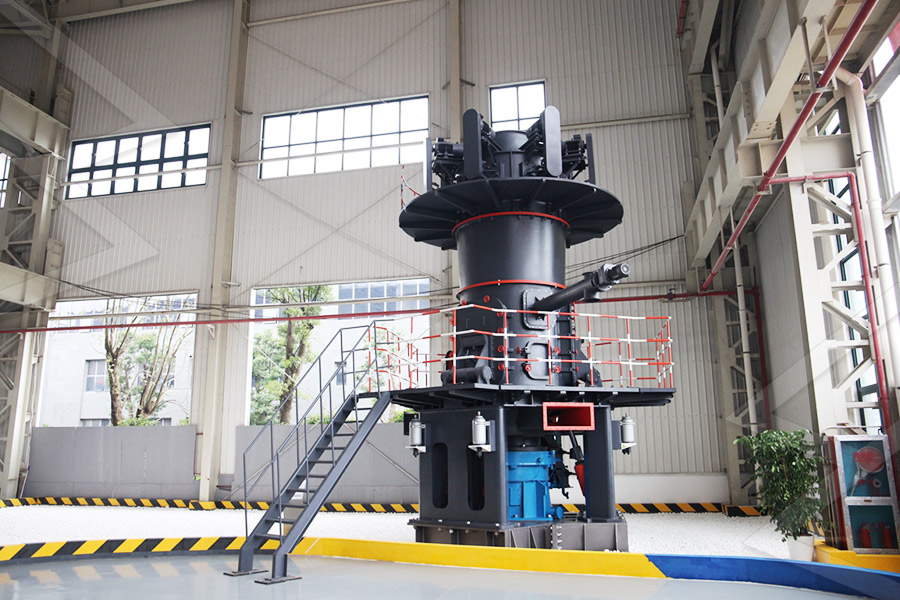
Stationary Crusher
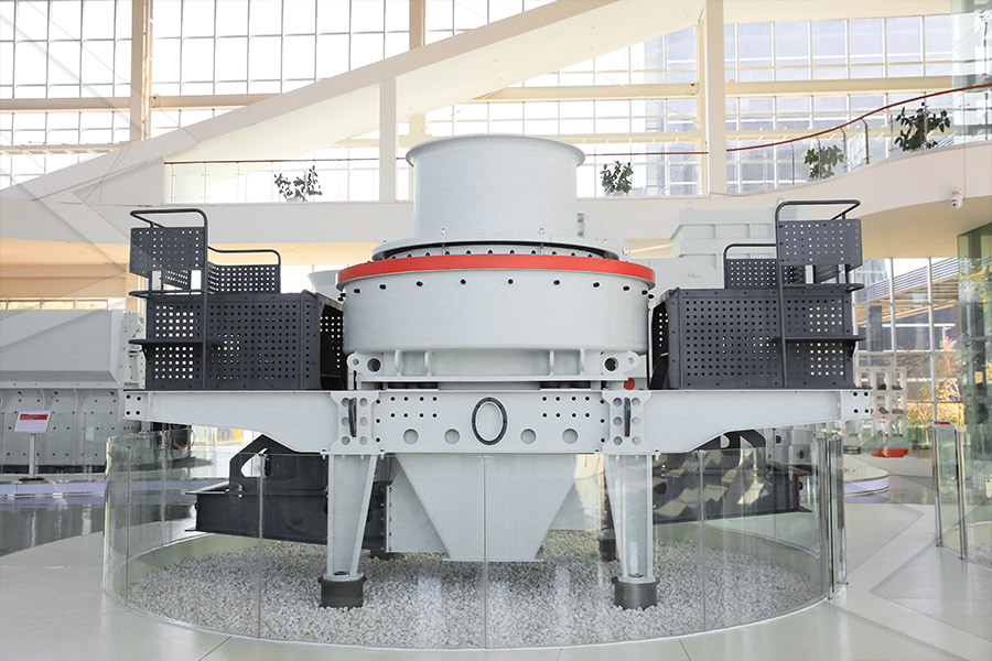
Sand making equipment
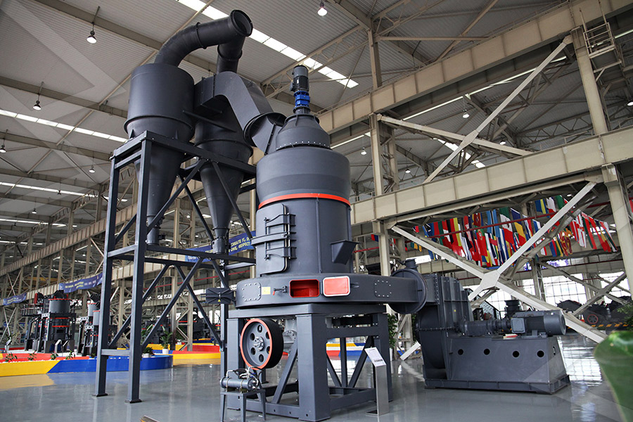
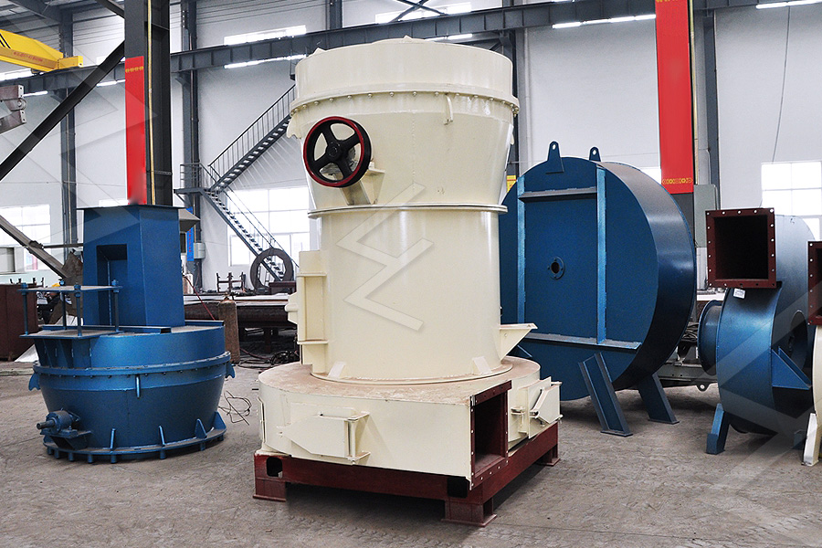
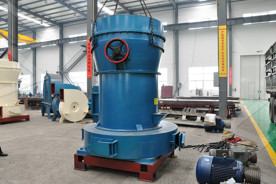
Grinding Mill
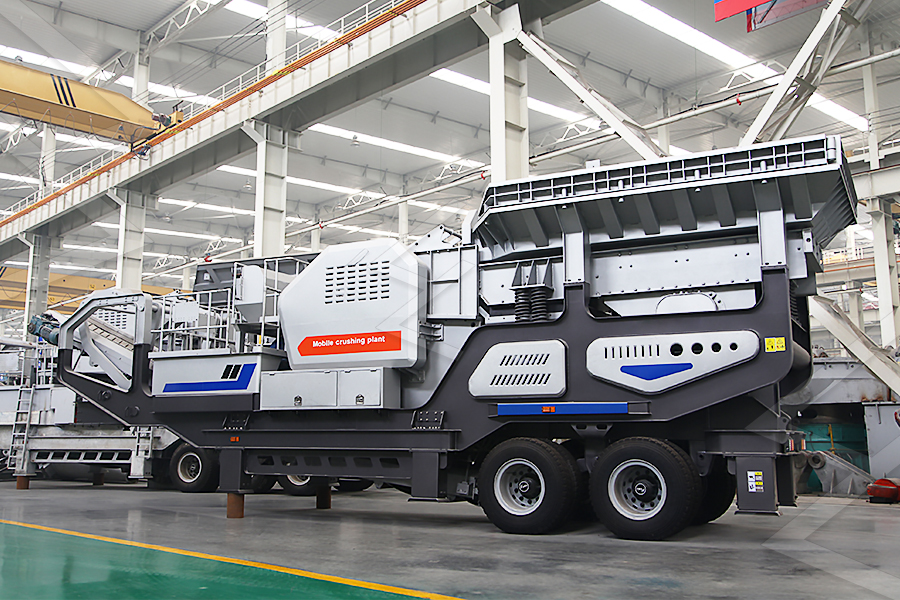
Mobile Crusher