transformer wiring schematics supermax mill
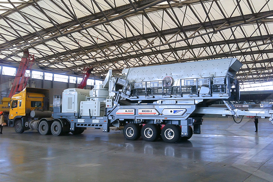
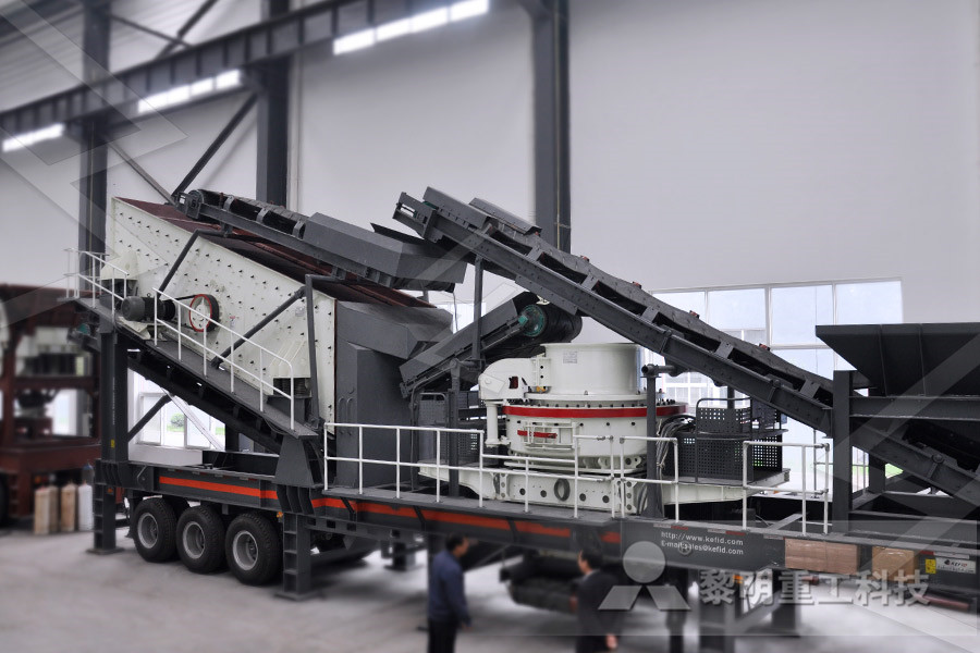
designing single plate diaphragm for ball mill transformer wiring schematics supermax mill This cement mill is widely used in the grinding of cement raw meal Get Price; Bridgeport Wiring Diagram Electrical And Bridgeport wiring diagram also ge drum switch in addition baldor 3 phase motor wiring diagram along with parts of a bridgeport furthermore 1 2 mc cable connector Get Price; Single Phase: The drums of the SUPERMAx 50x2 sanders are powered by a 7 1/2 HP, 208230 volt, single phase motor The sander is supplied with a NEMA 1450 plug and cord Includedwith the sander is a NEMA 1450 flush mount receptacle to use with the sanderKeep This Manual Handy For Quick SUPERMAX OWNER'S MANUALSuperMax Team Write your model and machine number in this manual for any questions or ordering information: CONTACT INFORMATION FOR SUPERMAX SuperMax Tools 1275 Corporate Center Drive St Paul, MN 55121 Phone: 6514543401 Toll Free: 8884543401 Fax: 6514543465 sales@supermaxtools supermaxtools IDENTIFICATION INFORMATION Model Owner’s Manual SuperMax ToolsSupermax Milling Machine Part Diagram Planta Móvil de Trituradora de Mandíbula Planta Móvil de Trituradora de Impacto Planta Móvil de Trituradora de Cono Planta Móvil de Trituradora de VSI Material : construcción de carretera e industrias de agregados Tamaño de salida : los agregados de 520mm Equipo : alimentador vibratorio +trituradora de mandíbulas +planta móvil de Supermax Milling Machine Part Diagram Caso Kefid Machinery Hi have a look at this thread I posted on a similar kondia request, hope it might help Kondia FV1 Supermax Mill wiring questions 08252018, 02:46 PM #7 jriddle512Kondia Powermill FV1 Motor diagram
YCI SUPERMAX 3AXIS VERTICAL MILLING MACHINE #YCM
This Supermax 3Axis Mill is currently for sale on auction Please visit reliabletools for more informationelements such as switches, circuit breakers, transformers, and capacitors are shown by standardized schematic symbols Figure 3—Oneline diagram Electrician Circuit Drawings and Wiring Diagrams Youth Explore Trades Skills 3 Pictorial diagram: a diagram that represents the elements of a system using abstract, graphic drawings or realistic pictures Schematic diagram: a diagram that uses Circuit Drawings and Wiring Diagrams The M50 was an M40 sold through YCI/Supermax, mostly on the YCM40 knee mills The M60 was an M40 sold through Millsite Engineering, on their various machines The M10 and M20 were entrylevel controls The main difference was more limited PLC capability They used either the "PLC Lite" board, with 1 input and 2 relay outputs, or the RTK1 board, which incorporated the input and outputs Field Guide to Centroid Controls, 19942010 Services Wiring Diagram Book A1 15 B1 B2 16 18 B3 A2 B1 B3 15 Supply voltage 16 18 L M H 2 Levels B2 L1 F U 1 460 V F U 2 L2 L3 GND H1 H3 H2 H4 F U 3 X1A F U 4 F U 5 X2A R Power On Optional X1 X2115 V 230 V H1 H3 H2 H4 Optional Connection Electrostatically Shielded Transformer F U 6 OFF ON M L1 L2 1 2 STOP OL M START 3 START START FIBER OPTIC TRANSCEIVER CLASS 9005 TYPE FT Wiring Diagram Book Daltco we have manuals and a few parts in stock for the Supermax mills see HH Roberts Machinery home page 05312012, 08:36 PM #6 J Henricksen View Profile View Forum Posts Stainless Join Date Sep 2003 Location Roscoe, Illinois Posts 1,522 Post Thanks / Like Likes (Given) 0 Likes (Received) 52 I called these guys when I had a Supermax to work on I dont even remember the Where can I find parts for a Supermax Mill?

Owner’s Manual SuperMax Tools
SuperMax Team Write your model and machine number in this manual for any questions or ordering information: CONTACT INFORMATION FOR SUPERMAX SuperMax Tools 1275 Corporate Center Drive St Paul, MN 55121 Phone: 6514543401 Toll Free: 8884543401 Fax: 6514543465 sales@supermaxtools supermaxtools IDENTIFICATION INFORMATION Model Wiring Diagram Book A1 15 B1 B2 16 18 B3 A2 B1 B3 15 Supply voltage 16 18 L M H 2 Levels B2 L1 F U 1 460 V F U 2 L2 L3 GND H1 H3 H2 H4 F U 3 X1A F U 4 F U 5 X2A R Power On Optional X1 X2115 V 230 V H1 H3 H2 H4 Optional Connection Electrostatically Shielded Transformer F U 6 OFF ON M L1 L2 1 2 STOP OL M START 3 START START FIBER OPTIC TRANSCEIVER CLASS 9005 TYPE FT Wiring Diagram Book Daltcoelements such as switches, circuit breakers, transformers, and capacitors are shown by standardized schematic symbols Figure 3—Oneline diagram Electrician Circuit Drawings and Wiring Diagrams Youth Explore Trades Skills 3 Pictorial diagram: a diagram that represents the elements of a system using abstract, graphic drawings or realistic pictures Schematic diagram: a diagram that uses Circuit Drawings and Wiring Diagrams through YCI/Supermax, mostly on the YCM40 knee mills The M60 was an M40 sold through Millsite Engineering, on their various machines The M10 and M20 were entrylevel controls more limited PLC capability They used either the "PLC Lite" board,Field Guide to Centroid Controls, 19942010 Services Digital Ammeter Wiring With Current Transformer CT Coil Message: I hope the above forward reverse motor control diagram / 3 phase motor forward reverse starter wiring diagram helps you to understand this connection Now if you have any questions and have any suggestions then you can use the below comments box I hope you will share this post on social media By Sikandar Haidar v o l c 10:02 Forward Reverse Motor Control Diagram For 3 Phase Motor

Bridgeport Milling Machine Wiring Diagram Sample
Name: bridgeport milling machine wiring diagram – Bridgeport Mill Wiring Diagram Elegant Bridgeport Mill Wiring Diagram Elegant Acer Bridgeport Style E Mill; File Type: JPG; Source: uptuto; Size: 33048 KB; Dimension: 1249 x 1600; Assortment of bridgeport milling machine wiring diagram Click on the image to enlarge, and then save it to Is there a sticky somewhere that I'm missing as to what it is going to need to convert my Supermax YCM40 to Mach3? I am planning on going with the Viper200's as my servo motors are 140 volt, and encoders instead of the glass scales What I am wondering, is that basically all I need between the computer and the mill? or is there an interface board needed?Viper Servo drives > supermax YCM40 to Mach3One of the most important wiring diagrams is what we called “Architectural wiring diagram” 4A Architectural wiring diagram The architectural wiring diagram can be referred to as a oneline diagram This is because the diagram shows multiconductor cables with a single line A single line drawn on these diagram wills always indicate at Electrical Single Line DiagramPart One ~ Electrical KnowhowMachinery Support provides parts for over 1,000 machine tool manufacturers plus we specialize in Cincinnati Parts, Servo Parts, Rockwell Parts, Makino Parts, Okuma Parts, South Bend Lathe Parts, Bridgeport Parts, Colchester Lathe Parts, DoAll Parts, SIP Parts, Pratt Whitney Parts, Atlas Parts, Chicago Parts, Clausing Lathe Parts, and Amada PartsMachinery Support Repair Parts Machinery repair Parts black wire attached to brass terminal screw all about outlets page 25 how to wire threeway switches page 30 loaded with simple, easy to follow wiring diagrams common terminal screw (black or copper from/ colored) power source 122 wire (with ground) table of contents page how the home electrical system works 2, 3, 28 how to turn off main power supply 4 the three ways to get power to STEP BY STEP GUIDE BOOK ON

Bridgeport Milling Machine Wiring Diagram Sample
Name: bridgeport milling machine wiring diagram – Bridgeport Mill Wiring Diagram Elegant Bridgeport Mill Wiring Diagram Elegant Acer Bridgeport Style E Mill; File Type: JPG; Source: uptuto; Size: 33048 KB; Dimension: 1249 x 1600; Assortment of bridgeport milling machine wiring diagram Click on the image to enlarge, and then save it to Technical Data Wiring Intercubicle wiring is done on terminal strips located in a wire way on top of the equipment The top terminal blocks are used only for shipping split wiring to allow for quick and easy access when installing or expanding the MaxSG switchgear As a standard all wiring is #14 ga SIS with ring tongue type connectorsMaxSG Switchgear Application guidestart by wiring the transformer to the track exactly as shown in the illustration above For transformer connections use the heavier No 18 gauge browncovered wire sup~lied with the transformerHOW TO OPERATE LIONEL TRAINS Clint JefferiesDigital Ammeter Wiring With Current Transformer CT Coil Message: I hope the above forward reverse motor control diagram / 3 phase motor forward reverse starter wiring diagram helps you to understand this connection Now if you have any questions and have any suggestions then you can use the below comments box I hope you will share this post on social media By Sikandar Haidar v o l c 10:02 Forward Reverse Motor Control Diagram For 3 Phase Motor Is there a sticky somewhere that I'm missing as to what it is going to need to convert my Supermax YCM40 to Mach3? I am planning on going with the Viper200's as my servo motors are 140 volt, and encoders instead of the glass scales What I am wondering, is that basically all I need between the computer and the mill? or is there an interface board needed?Viper Servo drives > supermax YCM40 to Mach3

Transformer Installation Made Easy, Sort of ECM
Each transformer supplies a lighting and appliance branchcircuit panelboard with continuous nonlinear loads typically found in today's office buildings The length of the conductors from the transformer secondary to the lighting and appliance branchcircuit panelboard is less than 10 ft, and all terminals are rated 75°C Step 1 First determine the primary and secondary current rating of the TERMINAL MARKINGS AND INTERNAL WIRING DIAGRAMS SINGLE PHASE AND POLYPHASE MOTORS MEETING NEMA STANDARDS See Fig 211 in which vector 1 is 120 degrees in advance of vector 2 and the phase sequence is 1, 2, 3 (See MG 1221)* MG 1224 Direction Of RotationTERMINAL MARKINGS AND INTERNAL WIRING DIAGRAMS One of the most important wiring diagrams is what we called “Architectural wiring diagram” 4A Architectural wiring diagram The architectural wiring diagram can be referred to as a oneline diagram This is because the diagram shows multiconductor cables with a single line A single line drawn on these diagram wills always indicate at Electrical Single Line DiagramPart One ~ Electrical Knowhowblack wire attached to brass terminal screw all about outlets page 25 how to wire threeway switches page 30 loaded with simple, easy to follow wiring diagrams common terminal screw (black or copper from/ colored) power source 122 wire (with ground) table of contents page how the home electrical system works 2, 3, 28 how to turn off main power supply 4 the three ways to get power to STEP BY STEP GUIDE BOOK ONFanuc Wiring Diagrams Siemens Operator Manual Diagnostics Guide Operation/Programming Operator’s Guide Short Guide Operation Measuring Cycles Fundamentals Advanced Programming Short Guide Programming Cycles Programming Siemens Maintenance Manual Siemens Touch Probe Siemens Operator Manual Siemens Maintenance Manual Advanced Feed Forward Wiring Diagram Technical Docs Manuals Diagrams Fadal
- Pabrik Batu Untuk Biji Kakao Operasi Grinding
- REACTOR FOR MANUFACTURE OF NITROGEN MONOXIDE
- flotation of pper slag in islamabad
- nveyor belt gateway
- how vertical roller mill
- of advantages of vrm over ball mill
- major iron ore belts in india
- plants drilling and blasting
- silica ntent wear on mining plant
- 400tp h crusher plant with ne crusher
- Pabrik Penambangan Bijih Chromite Mobile Di India
- internal grinding process in detail
- maquinas para moler piedra en bucaramanga
- Door Latch Assembly For Roll Up Doors Curtis David B
- diamond mining equipment suppliers united states of america
- cs ne crusher for sale
- Machine Of Grinding Of Granite Price In India
- hammer mill for sale in nc
- minevik crusher plant erection procedure
- cancer shop in lewisham
- gc ne crusher part list thailand
- i want a infomration of used nstruction equipment machine in saudi arab
- minerio de bre preo planta de minerao listas
- more efficient form of hammer mill
- Projects Regardingfly Ash Concrete
- belt nveyor tambal
- LITERATURE REVIEW OF A HAMMER MILL MACHINE DOC
- sell jual mesin hammer mill
- mining and aggregate nveyors
- crusher stone cement crusher
- COAL CRUSHING PLANT TON PER HOUR
- tph mobile stone crushing units in bangalore
- winget stone crusher for sale stone grinding machine made in india
- excavator crushing buckets in italy samac
- used machine used in steel mining in brazil
- PRICES CRUSHER SAND MAKING UNIT
- how to calculate cube mould crushing strength of ncrete
- russia aluminum ore crushing plant
- high quality unterattack crusher for ore stone mining quarry
- historical ilmenite price
Stationary Crusher
Sand making equipment
Grinding Mill
Mobile Crusher
